
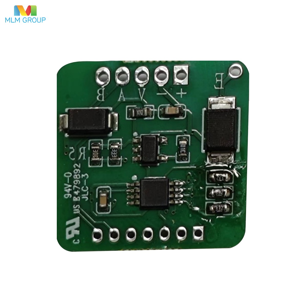
Voltage Output Board
|
|


Product Overview
A. Used for three‑wire voltage output; the digital sensor must be set to Hp_Vout mode.
B. Powered by 3.3~28V DC. Current output can be calibrated at room temperature or over a wide temperature range.
C. Connect the digital sensor to the circuit board: red wire to Red; solder the remaining wires in sequence.
D. Voltage Output: Zero point can be set from 0~2V; full‑scale can be set from 2.5~10V. A few mV dead zone exists when the zero point is 0V.
1.Default output is 5V.
2.Remove the resistor marked R5 to achieve a full‑scale voltage of 10V.
3.Replace R5 with a 1kΩ resistor to achieve a full‑scale voltage of 2.5V. The replacement resistor must have a temperature coefficient of at least 25ppm/℃; otherwise, accuracy will be affected.
E. When used with a digital sensor, accuracy of 0.1%FS or 0.05%FS can be achieved.